Upload bitstream from Arduino IDE
If you have FPGA board with JTAG adapter (either onboard or external) supported by OpenOCD then we can offer a simple procedure of uploading bitstreams to FPGA from pull down menu. Download bitstreams for your boards and place them in directory arduino-1.6.x/hardware/fpga/f32c/bootloaders, file paths looking like thisarduino-1.6.x/hardware/fpga/f32c/bootloaders/tb276/tb276_mips_81mhz.sof arduino-1.6.x/hardware/fpga/f32c/bootloaders/tb299/xc6slx9_mips_81mhz.svf |
Select Tools->programmer as ujprog (FPGArduino), that should be common to all our FPGArduino boards
Select the board e.g. Tools->Board->TB276
Select the JTAG openocd interface type e.g. Tools->OpenOCD JTAG->FT2232 (currently we list only Altera Blaster and FT2232 cable) but you may add your own by editing boards.txt
Select the upload destination and upload tool, e.g. SRAM (openocd)
Select Tools->Write Bootloader
If LEDs on FPGA board start to alternatively fade in 2 groups of 4 then
*** congratulations! ***
You have successfuly uploaded and activated arduino compatible F32C bitstream. You may continue downloading and installing f32c gcc compiler, and try to upload your first arduino blink led example.
Arduino IDE uses commandline tools like openocd, xc3sprog, quartus_pgm to upload bitstream. Commands are in boards.txt. OpenOCD version 0.8.0 on debian was working well and then came version 0.9.0-rc1 which seems broken with Altera Blaster. It will freeze the IDE due to waiting forever in attempt to initialize. If this happens you can unblock it with
killall -9 openocd |
SRAM can be uploaded either with openocd tool (normally found in all major linux distributions) or with quartus_pgm tool (you will need to take a day off, register yourself to Altera, start with 15 GB free disk space, download and install Quartus II for linux). TB279 FLASH can be uploaded with Quartus II. We don't know how to do it from OpenOCD. Our reference board ULX2S will use our ujprog to write to FLASH on lattice FPGA. For other boards we have supported only uploading to SRAM. We don't know how to write to FLASH from linux and invite you to help.
FPGA bitstreams
The first stumbling block for newbie FPGA user is how to upload the synthesized binary code (bitstream) to the FPGA, also known as "flashing".Bitstream is a pre-compiled binary image which needs to be loaded to internal SRAM of the FPGA chip. In this case the bitstream contains internal hardware definitions for F32C CPU core with simple bootloader and all basic hardware like serial ports, gpio, timers etc (SoC).
Simply speaking it will instruct FPGA chip to reconfigure itself into arduino compatible system. Uploading bitstream to FPGA is similar to uploading bootloader on arduino board.
For example, one bitstream may contain arduino with MIPS CPU, second with RISC-V CPU, third can run at higher clock speed and so on.
FPGA chips need to load internal SRAM with bitstream. It can be loaded using external or onboard JTAG programmer. Most FPGA boards can load bitstream at power on from onboard FLASH chips, internal FLASH in FPGA chip, SD card, microcontroller, etc.
For a quickstart, just load bitstream to SRAM of FPGA and test it. It will load in few seconds and makes no permanent change to the board.
When permanent storage of the bitstream is needed, it is not so simple. Some boards require proprietary tools like Quartus_PGM for Altera or Xilinx IMPACT, found as small binaries in several GB large software packages with IDE for FPGA synthesis like Quartus II or Xilinx ISE. Those tools may send some bistream image to FPGA to create a JTAG-to-FLASH bridge. Propriatery tools require a supported JTAG programmer, some are quite expensive.
Hardware: JTAG programmers
Low cost $30 FPGA boards like TB276 (Altera Cyclone-4) or TB299 (Xilinx Spartan-6) need external JTAG programmer. Readily useable USB JTAG Programmer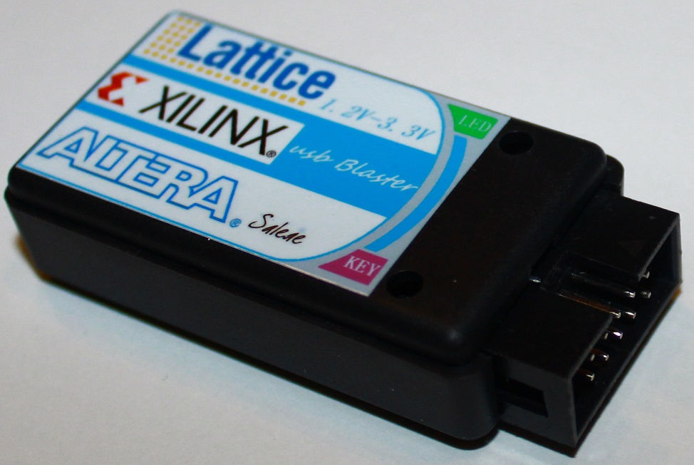
Instead of buying board+programmer for the similar price you might consider getting a better equipped entry-level FPGA board with many other useful things like RAM, connectors, buttons, leds, SD slot, display, including the onboard USB JTAG programmer like FT2232 supported by OpenOCD. Some boards with FT245R like our FER/RIZ ULX2S currently lack a good OpenOCD support, but with freely available board-specific JTAG tool like UJPROG for Windows OSX Linux-i686 Linux-x86_64 this small board will make a good bang for the buck.
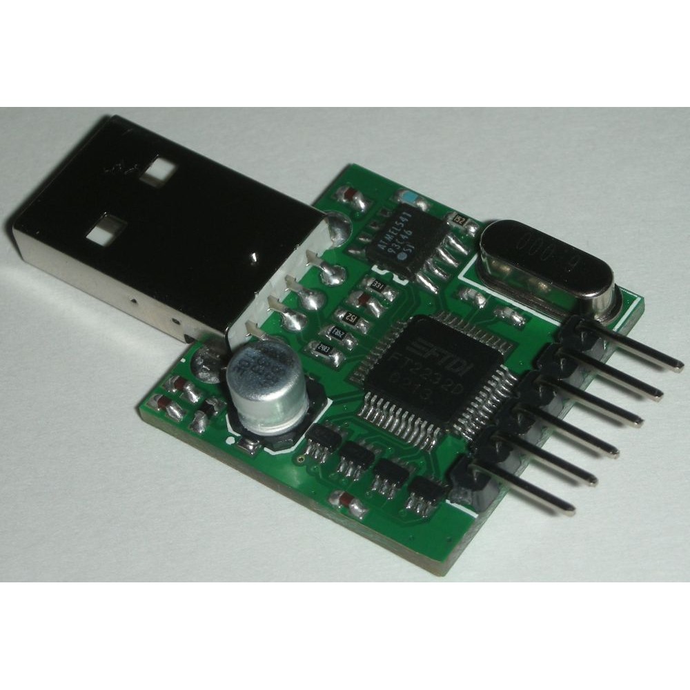
Any FT2232 adapter
| PIN | FT2232 FPU1 JTAG | FPGA TB276 | FPGA TB299 |
| VCC/VREF | 6 | 4 | 2 |
| GND | 5 | 10 | 1,3,5,7,9,11,13 |
| TCK | 4 | 1 | 6 |
| TDO | 3 | 3 | 8 |
| TDI | 2 | 9 | 10 |
| TMS | 1 | 5 | 4 |
/usr/share/openocd/scripts/interface/ftdi/
If neither of above works for boards like ZYBO, that could be because additional GPIO pins of FT2232 are used to control some undocumented hardware, see the manual page 7 intentionally left blank a nice touch from the manufacturer. So calm down and experiment several days and nights with line
ftdi_layout_init 0xc01d 0xcafe
and you might come up with
# # ZYBO ft2232hq usbserial jtag # interface ftdi ftdi_device_desc "Digilent Adept USB Device" ftdi_vid_pid 0x0403 0x6010 ftdi_layout_init 0x3088 0x1f8b ftdi_layout_signal nSRST -data 0x3000 -oe 0x1000 ftdi_layout_signal LED -data 0x0010 reset_config srst_pulls_trst |
Cypress FX2 CYC68013A
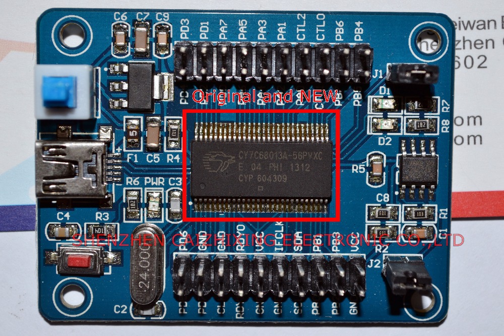
However, cycfx2prog or fxload can temporarily upload firmware into RAM of this board. This can be automated using an udev rule and it will appear as Altera Blaster few seconds after plug-in. To compile the cypress firmware, older sdcc compiler (version 2.9.x), might be required which is in debian still available as a package with a cryptic name cc1111
Some Xilinx boards like Starter-3 series have also onboard CYC68013A but it needs closed source firmware and bitstream for onboard CPLD chip between cypress and Spartan-3. Some considerable amount of reverse engineering has taken place which produced xc3sprog now available in most linux distributions. It will upload bitstream to Spartan-3 starter boards and probably many others just like this:
xc3sprog -c xpc bitstream.bit |
# Xilinx platform cable
# cypress FX2 -> CPLD XC2 -> jtag XC3

# when inserted empty device 0x03fd:0x000d then load firmware
# uncomment either cycfx2load or fxload line
# or have both commented if you don't want to load firmware
# when device is inserted into usb

# cycfx2load will load firmware
SUBSYSTEM=="usb", ENV{DEVTYPE}=="usb_device",
  ATTRS{idVendor}=="03fd", ATTRS{idProduct}=="000d",
  RUN+="/usr/bin/cycfx2prog -id=03fd:000d prg:/usr/local/xilinx/14.7/ISE_DS/ISE/bin/lin/xusb_emb.hex run"
# fxload will load firmware
# SUBSYSTEM=="usb", ENV{DEVTYPE}=="usb_device",
#   ATTRS{idVendor}=="03fd", ATTRS{idProduct}=="000d",
#   RUN+="/sbin/fxload -v -t fx2 -I /usr/local/xilinx/14.7/ISE_DS/ISE/bin/lin/xusb_emb.hex -D vid=0x03fd,pid=0x000d"
# when firmware is loaded, green led near usb connector on Digilent Spartan 3AN Starter kit should be lit
# and this command will list some jtag devices
# xc3sprog -c xpc
# JTAG loc.:   0  IDCODE: 0x22628093  Desc:                      XC3S700AN Rev: C  IR length:  6
# JTAG loc.:   1  IDCODE: 0xf5046093  Desc:                         XCF04S Rev: O  IR length:  8

# when device with firmware reloads as 0x03fd:0x0008 give it dialout group permission
# non-root users that belog to dialout group can access jtag
SUBSYSTEM=="usb", ENV{DEVTYPE}=="usb_device",
  ATTRS{idVendor}=="03fd", ATTRS{idProduct}=="0008",
  GROUP="dialout", MODE="0664"
|
WiFi ESP8266
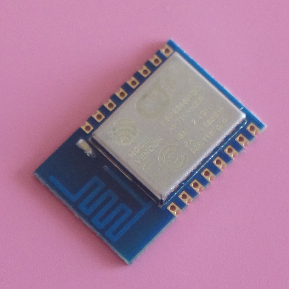
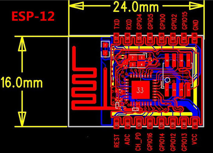
| PIN | nodemcu JTAG | ESP-12 JTAG | FPGA TB276 | FPGA TB299 |
| GND | GND | GND | 10 | 1,3,5,7,9,11,13 |
| TMS | D0 | GPIO16 | 5 | 4 |
| TDI | D7 | GPIO13 | 9 | 10 |
| TDO | D6 | GPIO12 | 3 | 8 |
| TCK | D5 | GPIO14 | 1 | 6 |
| VCC | NC or VCC | VCC | 4 | 2 |
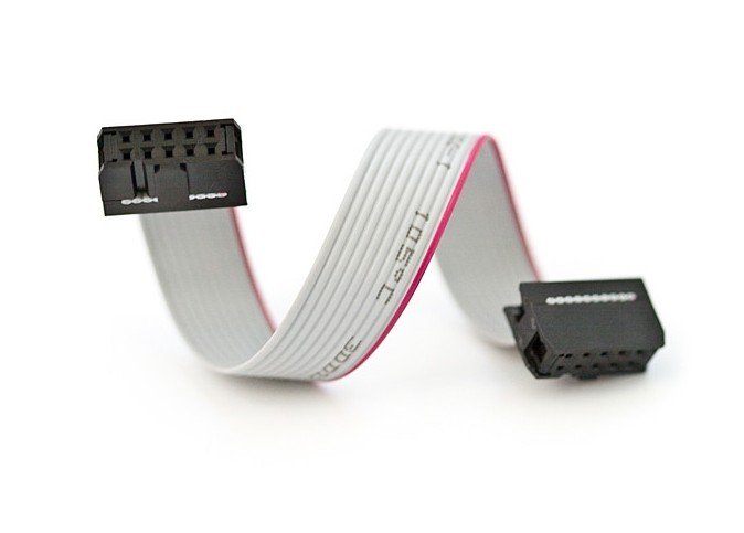
Connecting
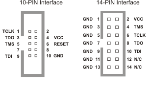
If FPGA board has USB programming connector, plug it in your computer USB, find out what interface it uses using lsusb or googling, optionally get board schematics and skip the rest of this section.If you have external JTAG programmer, it is best to obtain a suitable flat cable for JTAG that directly connects programmer to the board. Altera TB276 uses classic straight 10-pin flat cable and Xilinx TB299 similar 14-pin flat cable.
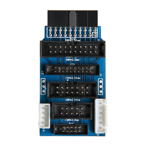
If pinouts or connectors don't match, you may need some adapter board
Or you can opt to find out the pinout of the programmer and the FPGA board and connect them manually with color female-to-female jumper wires
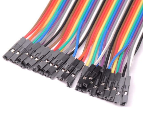
FPGA board has reverse signal directions versus the programmer. Pins of the same name on the programmer and the FPGA board should be connected together. Sometimes names migh be slighty different, you should recongnize them as the same signal like TCK is sometimes named TCLK for example.
We suggest to first download pinouts, prepare a list of signal names and pin numbers telling which pin of programmer connect to which pin of the FPGA board. For each pin use wire of different COLOR. In case of wrong wiring it will just not work if you are lucky, but may also permanently damage boards if you mess up GND and VCC so double check before powering up.
Voltage of the JTAG programmer must match the required FPGA JTAG voltage. Voltage at signal pins can be either 0V (logical low) or same as VCC pin (logical high). Most FPGA boards will work with 3.3V but some might need other voltage like 1.8V so be careful.
Some better JTAG programmers (like FT2232 FPU1) will read VCC from FPGA board and adapt its logical high voltage level to be equal to the board VCC voltage.
Some cheapest JTAG (like cypress LCSOFT) ignore VCC and always output a fixed logical high value of 3.3V.
Putting 3.3V JTAG programming voltage to 1.8V FPGA may cause permanent damage.
USB Permissions and firmware
USB JTAG devices on usual linux installations need a permission to be accessed as ordinary user. You can google or create yourself an udev rule that sets permissions and if necessary also uploads firmware for some JTAGs upon hotplug.Upload bitstream from commandline using make
If you build bitstreams from commandline using makefilef32c/rtl/proj/altera/tb276 f32c/rtl/proj/xilinx/tb299_bram f32c/rtl/proj/xilinx/zybo_bram f32c/rtl/proj/lattice/ulx2s_sram |
make program make xc3sprog |
make flash |
Using OpenOCD
OpenOCD is a general-purpose tool which primary function was to interface over JTAG to the on-chip debugger of ARM and MIPS processors.But it can also communicate to various onboard chips connected to a common JTAG chain, like a small local network.
FPGA can be familiar member of onboard JTAG chain. ARM and FPGA sometimes are integrated in the same chip, as ZINQ for example. FPGA industry standardized a bitstream format named SVF in order to support third-party JTAG uploaders. OpenOCD supports some useable subset of SVF. SVF contains raw sequence of JTAG commands.
OpenOCD uses TCL as scripting language so every config file is just a simple TCL script, often in simplest form of lines where first word is a function name followed by optional space-delimited argument list:
# some comment interface ftdi # another comment ftdi_device_desc "Digilent Adept USB Device" ftdi_vid_pid 0x0403 0x6010 ... |
There's directory containing some ready-made config files for various known interfaces, boards and other groups of hardware.
Each file can be executed in sequence using one or more commandline options --file=filename
Common bitstream upload procedure may be described as this sequence of config files:
1. setup JTAG hardware interface
2. setup TAP (board's JTAG chain with expected chip ID)
3. upload a bitstream SVF file to the FPGA TAP
4. shutdown JTAG interface and exit
files are first searched in /usr/share/openocd/scripts then in local local directory where OpenOCD runs for example
openocd \ --file=interface/ftdi/jtagkey.cfg \ --file=board/cpld/xilinx-xcr3256.cfg \ --file=upload_bitstream_svf_file.cfg \ --file=shutdown_and_exit.cfg |